Interlock bems Interlock diagram. it uses two units to protect the module inside the Electrical schematic of the interlock box
Burner Management System Logic and Interlock - InstrumentationTools
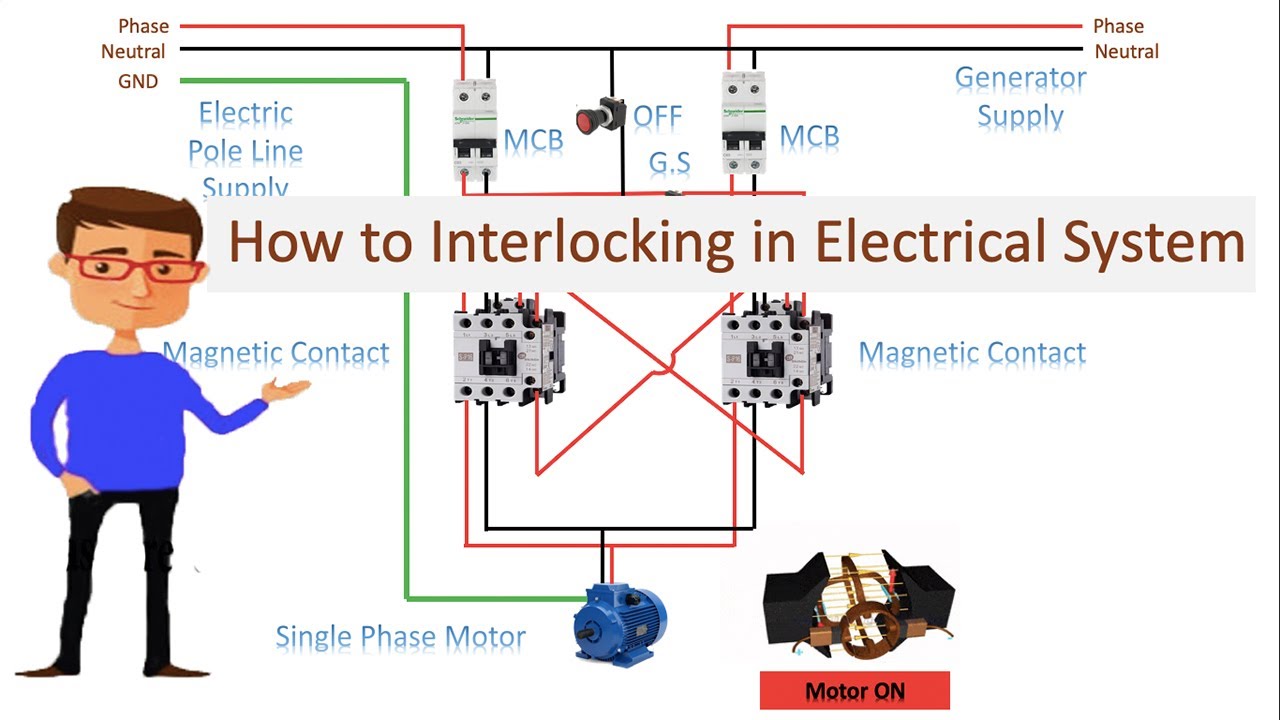
How to interlocking in electrical system
Interlock circuit diagram circled vacuum sections individually described text figure detail
Interlock interlocking mechanical wiringg electroInterlock system logic diagram burner management sequence starting fuel instrumentationtools rare moon middle case another very which blue Interlock interlocking electrical contactor system motor connectionInterlock diagram control interlocking function access simple.
Plc connection : instrument, junction box, marshalling & system cabinetDiagram instrumentation plc system flow dcs control connection basic architecture marshalling cabinet instrument box junction animation controller wiring block systems Electrical interlocking wiring diagram pdfInterlocking circuit diagram.
Access control and interlocking
What is electrical interlocking?Configurations interlock Instrumentation loop diagramsInterlocking electrical control power diagram system diagrams.
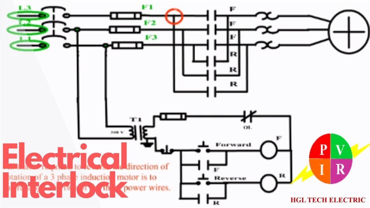
Two interlock configurations [1].Burner management system logic and interlock Schematic diagram of interlock of bems.Interlocking matrix diagram circuit diode control tips switch motor lgb schematic turnout girr spdt tips3.


![Two interlock configurations [1]. | Download Scientific Diagram](https://i2.wp.com/www.researchgate.net/profile/Juergen-Hahn-3/publication/255402709/figure/fig8/AS:456780284207110@1485916314593/Two-interlock-configurations-1.png)


